breadcrumb
Content SDK component is missing React implementation. See the developer console for more information.
INTRODUCTION
Who can forget the image of Steve Bradbury winning gold in the 1000m ice skating event at the Salt Lake Winter Olympics in 2002?
It’s an extraordinary story that is one of the greatest moments in Australian sporting history. For those who remember watching the event on TV, it’s a sobering thought to acknowledge that this happened 15 years ago.
So it is even more surprising that it took this amount of time to update the switchboard standard from the previous AS/NZS 3439 to the current AS/NZS 61439 series of standards.
Having skipped two generations of the IEC 60439 series updates – on which the AS/NZS standards are based, meant that we had lots of catching up to do, much like Steve Bradbury himself.
The good news is that the final update was published in 2016, and with it comes a number of distinct changes to make the process of specifying and building a switchboard much clearer than ever before. So it was well worth the wait!
Prior to the publication of AS/NZS 61439 the switchboard standard was previously revised in 2002!
RELEVANCE TO IEC AND PAST STANDARDS
The AS/NZS 61439 series of standards are managed by a dedicated selection of industry subject matter experts who form subcommittee EL6-8. The subcommittee comprises of people who have a broad range of experience in switchboards, from testing laboratories, switchboard manufacturers, consultants, contractors and suppliers. Whilst the AS/NZS electrical standards are predominantly based on international documents, we are fortunate that experienced members from EL6-8 also participate in the IEC committee that governs the 61439 series of standards. This process ensures that our local requirements are addressed in the appropriate manner. The old AS/NZS 3439 standards have been replaced by the new AS/NZS documents as detailed below, which are based on the equivalent IEC versions.
The most important attributes of the new AS/NZS 61439 series of standards can be summarised as follows:
- A new User Template is included to facilitate the creation of a customer specification
- The final switchboard design must be verified using one of a number of permitted methods
- The main busbar permissible operating temperature rating has been increased
- The forms of separation have been expanded to include images for use with circuit breaker chassis
- The arc fault containment options have been expanded to allow the international variant based on TR61641
These attributes will be explored in further detail throughout the sections defined within this Technical News
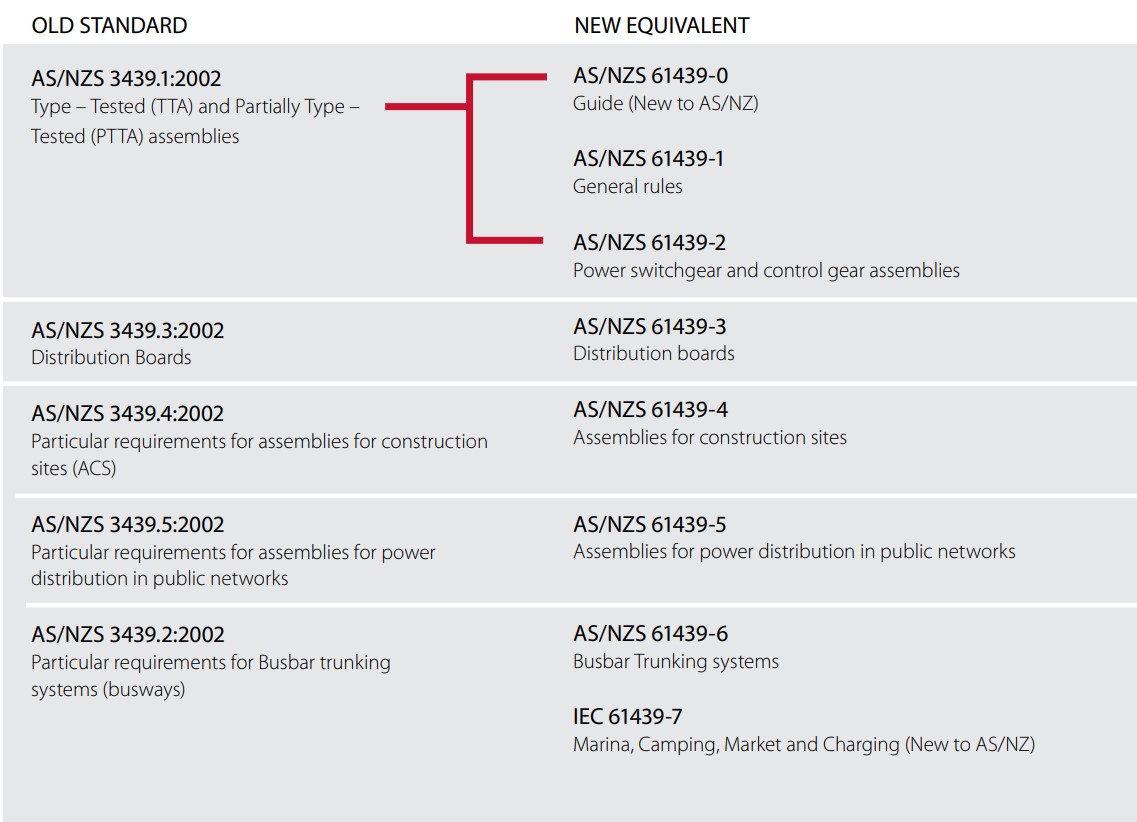
Figure 1 - Old AS/NZS 3439 vs. New IEC 61439
SECTION 1: HOW TO SPECIFY YOUR NEW SWITCHBOARD - USE ANNEX C TEMPLATE
The User Template Annex C, Figure 2 is scoped in AS/NZS TR61439.0:2016 and AS/NZS 61439.1:2016. New to AS/NZS, this template simplifies the switchboard specification using a list of parameters that are covered in the following headings:
Electrical Systems (i.e. V, I, f, earthing, etc)
Short circuit withstand capacity
Protection against electric shock
Installation environment
Installation method
Storage and handling
Operating arrangements
Current carrying capacity
The extract below illustrates the methodology applied when utilising the templates. The consultant, end user and manufacturer can use this document to agree to the specification for the final build. For example, within the “Electrical Systems” category, the first specification requirement suggests the selection of “Earthing System” configuration.
Clause 5.2 describes the requirement in detail
The default arrangement is suggested as “manufacturer’s standard” or “local requirements”. In some instances, other standards may apply, such as AS/NZS 3000 which is applied for general electrical installations or AS/NZS 3007 which is applied to mining electrical installations
The options listed in the standard are suggested
The final column lists the “agreed” specification for the customer’s requirements
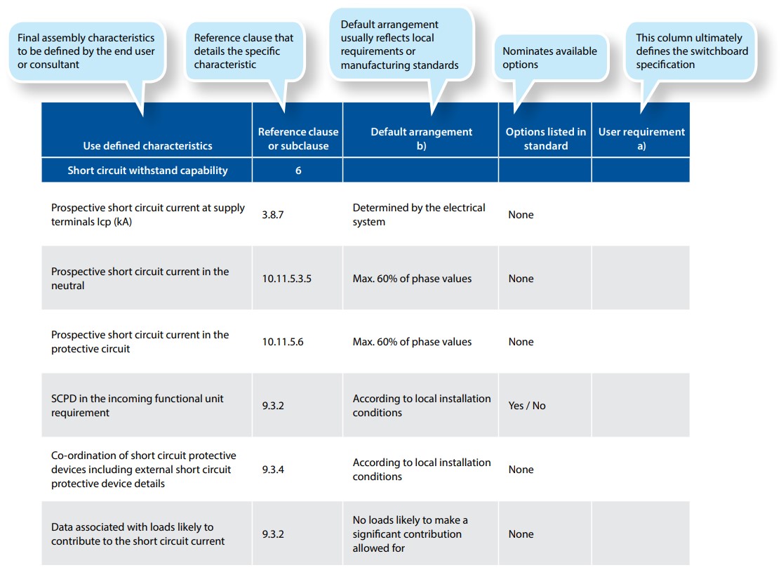
Figure 2 - Table C.1: Items subject to agreement between the assembly manufacturer and the user (Ref: AS/NZS 61439.1: 2016)
SECTION 2: HOW TO CHECK COMPLIANCE - USE ANNEX D VERIFICATION
In accordance with the previous AS/NZS 3439 standard, the final switchboard assembly was identified as a “type tested” or “partially type tested” assembly. The switchboard builder was required to produce documentation that could validate the claimed testing designation in accordance with Table 7 from AS/NZS 3439.
This terminology no longer applies and has been replaced by “verification”. Verification consists of documentation that validates the “design” criteria, supported with “routine” verification which is a reflection of materials and workmanship. The end user needs to be satisfied that the verification covers all specified aspects of the project requirement.
Verification
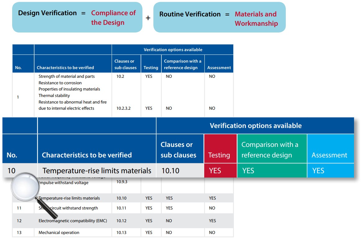
Figure 3 - Table D.1: List of design verifications to be performed (Ref: AS/NZS 61439.1: 2016)
Table D.1 (as published in AS/NZS 61439.1:2016) contains 13 key attributes that need to be verified to comply with the specified requirement. Each attribute can be verified by one or more different methods as indicated in Table D.1:
- Testing
- Calculation or comparison to a tested design (extrapolation)
- Assessment
The alternative verification methods are stipulated within Table D.1. More common requirements, such as temperature rise limits and short circuit withstand capacity can be verified by these methods. Some of the more specific requirements relate to the mechanical properties of the switch board, which is more detailed than in previous standards.
For instance, the following mechanical properties can only be verified by testing:
- Mechanical impact (IK test in accordance with IEC 62262)
- Lifting
- Resistance to corrosion (i.e. coating systems)
- Properties of insulating materials
Temperature Rise Verification Example
Whilst testing a switchboard is the most effective method of declaring a higher performance rating for an engineered design, it can also be the most expensive and time consuming option. Fortunately, the new standard details how to verify a design based on extrapolating previously tested configurations or by completing appropriately detailed engineering calculations. The clauses in the standard are used to assist in completing the verification process.
VERIFICATION BY DERIVATION
Clause 10.10.3: Derivation of ratings for similar variants
Typically, functional units have similar properties if all other factors remain identical, such as switchgear frame sizes, volumetric dimensions, mounting arrangements, size and cross sectional area of conductors. Frequently, the largest rated switchgear device within a specific frame size is used to conduct a test and thereafter any lower rated device in the same physical frame size can be used within the same module. An assembly can be verified if it has been built in accordance with a previously tested structure, assuming that the derivation has allowed for the following criteria (as extracted from AS/NZS 61439.1 Clause 10.10.3.2):
- The functional units shall belong to the same group as the functional unit selected for test (see 10.10.2.2.3)
- The same type of construction as used for the test
- The same or increased overall dimensions as used for the test
- The same or increased cooling conditions as used for the test (forced or natural convection, same or larger ventilation openings)
- The same or reduced internal separation as used for the test (if any)
- The same or reduced power losses in the same section as used for the test
This same logic applies if the switchboard manufacturer can no longer source the original tested switchgear device (usually an MCCB or contactor/overload) and would like to install the new model sourced from the same manufacturer, or devices fitted with alternative trip units. This substitution methodology is covered in Clause 10.10.3.5 and specific AU/NZ comments in Annex ZA.
The device substitution requirements for AS/NZS 61439 standard differs from the IEC standard on which it is based. In Australia and New Zealand, short circuit protective devices from another manufacturer may be substituted if the conditions of Figure 4 are satisfied, and the manufacturer of the substituting device has declared a current limiting characteristic equal to or better than the original device.
Whilst it is permissible to use substitute switchgear, the intent of the standard is to provide guidance when the original device (as tested) is no longer available or superseded. The onus is on the device manufacturer to validate the performance claims of a new device compared to the older device. It is definitely not the intent to allow for a type tested board fitted with brand “X” to be entirely substituted with brand “Y”, and then claim verification.
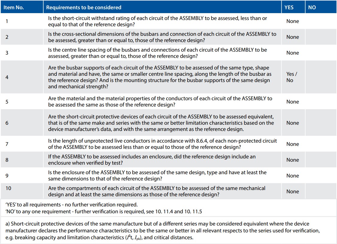
Figure 4 - Extract from Table 13: Short circuit verification by design rules check list (Ref: AS/NZS 61439.1: 2016)
VERIFICATION BY CALCULATION: SINGLE COMPARTMENT < 630A
For a single compartment of less than 630A rating, if we have not previously tested the assembly or device and/or do not wish to test the configuration, then these two options are available. In both instances, the engineer must account for the watts loss of all components that will be contained within the cell in order to determine the ambient temperature and subsequent impact on the performance of installed components.
Clause 10.10.4.2.1: Calculate watts loss of components within a compartment and determine ambient internal temperature
Whilst testing is not required in this instance, the verification process demands that the switchboard engineer can demonstrate due diligence when calculating the rated outcome. There are specific criterias that needs to be met when applying this verification method, including:
• The rated currents of the assembly shall not exceed 80% of the free air rating of the components
• The power loss data for all installed componentry is available and accurate
• Air flow and manufacturer’s installation tolerances are satisfied
• Eddy-current and hysteresis losses are minimised for any conductors carrying more than 200A
• Conductors have a minimum cross sectional area of 125% of the permitted current rating, where cables are selected in accordance with IEC 60364-5-52
• The temperature rise and power loss within the enclosure can be validated by the manufacturer or determined in accordance with Clause 10.10.4.2.2
Clause 10.10.4.2.2: Calculate watts loss of components, represent these with resistors and measure ambient internal temperature
This method requires that the switchboard manufacturer measures the temperature rise within a given enclosure design fitted with heating elements that replicate the watts losses of the proposed components. Thereafter, the final rating of the compartment will be determined by the impact of the measured ambient temperature on the installed components in accordance with the switchgear suppliers’ derating charts.
VERIFICATION BY ASSESSMENT: MULTIPLE COMPARTMENT < 1600A
For larger assemblies up to 1600A, the temperature rise can be calculated from the total power loss of installed components using the method detailed in AS/NZS 60890-2009. This standard is relatively easy to follow and includes a worked example in Figure 5, as illustrated right. The switchboard manufacturer can adopt this calculation as a method of verification without the requirement for further testing.
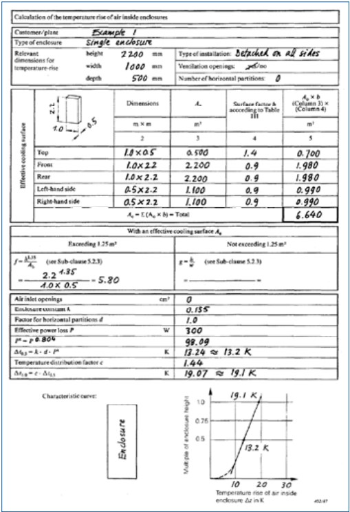
Figure 5 – Annex A (Ref: AS/NZS 60890: 2009)
SHORT CIRCUIT VERIFICATION BY CALCULATION
Short circuit testing for assemblies is the fundamental manner of determining the performance rating for a busbar system. In simple terms, verification test is designed to measure the mechanical withstand of the busbar supports. When short circuit current flows through a length of copper, there are two specific outcomes:
- The bar is subject to mechanical forces that can potentially bend the bar. If the magnitude of the current is too great for the busbar it will deform.
- The bar will increase in temperature. If the duration of the short circuit is too long, the bar will overheat and anneal or start to melt.
A well designed busbar system with the appropriate support mechanism will sustain a given fault level for a specified duration.
Clause 10.11.4 describes how a tested busbar assembly can be then used to extrapolate short circuit withstand ratings for similar bar designs by comparison to a tested reference design. This is particularly useful when extending a bar or fabricating connection tags between compartments or ACB cradles. The extract from Figure 6 below illustrates how the parameters from the tested configuration are used to calculate the withstand strength of untested busbars, when used in accordance with IEC 60685-1. A busbar rating can be retained when the distance between busbar supports (I1) is reduced, or when the separation between busbars (a) is increased. It is also possible to extend the total busbar length when the busbar supports are spaced in accordance with the original test parameters. The calculation methodology as described in IEC 60685-1 is acceptable as verification for this purpose. It is also worth noting exceptions that do not require further verification, namely:
- Assemblies that have a rated short-time withstand current or rated unconditional short circuit current not exceeding 10 kA r.m.s
- Assemblies that are protected by current- limiting devices having a cut-off current not exceeding 17kA at the maximum allowable prospective short circuit current at the terminals of the incoming circuit of the assembly
- Small control panels where the transformer rating is less than 10kVA & >110V or 1.6kVA & <110V
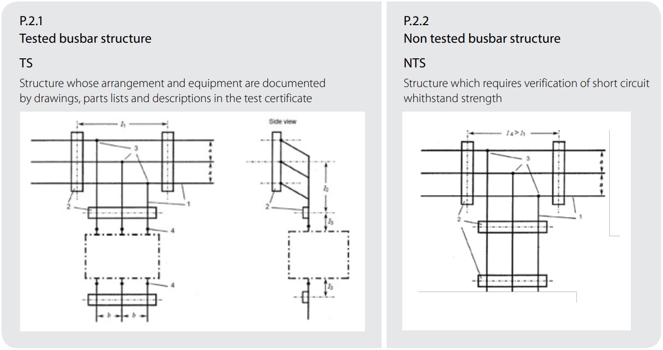
Figure 6 – Extract for Annex P (Ref: AS/NZS 61439.1: 2016)
SECTION 3: FORMS OF SEPARATION
The switchboard forms of separation are defined in AS/NZS 61439.2. The various designations describe how busbars, conductors, terminals and functional units are segregated from each other. The main forms are illustrated in Figure 7.
Chassis systems or similar are often used for miniature circuit breaker and MCCB feeder circuits. Unique to Australia and New Zealand, the suffix “i” and “h” have been included in our local standards to enhance the definition of the forms of separation when these types of assembly construction are used.
The “i” designates that the “insulation” on the main busbar is used as a barrier, whereas the “h” designates that the circuit breaker housing is used as the barrier. The Forms of Separation have been updated in the new AS/NZS 61439 series to include images that are applicable to chassis systems. Figure 8 contains the chassis images and definition of attributes. These images simplify the selection of the forms of separation for the specifier/ end user.
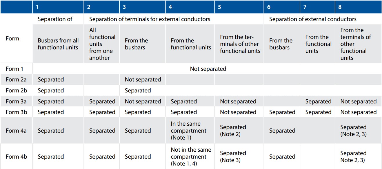
Figure 7 – Extract from Table 104.101: Minimum requirements for internal separation (Ref: AS/ NZS 61439.2: 2016)
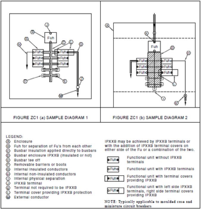
Figure 8 – Appendix ZC (Ref: AS/NZS 61439.2: 2016)
The selection of a particular Form of Separation is determined by the end user’s requirements for continuity of service. For example, if an assembly can be isolated for maintenance, Form 1 may be sufficient. If an assembly supports a critical process and it is desirable to keep some circuits operational while others are maintained, a higher Form should be selected. An end user should be encouraged to seek professional advice when selecting a specific form of separation.
What is the form of separation for the distribution board below?
In this example, the distribution board is designated as Form 4ah. To arrive at this conclusion:
- MCBs are represented on the left hand side of the Form 4ah from AS/NZS 61439.2 Appendix ZC, i.e. the standard device has IPXXB terminals and does not require additional terminal covers.
- The main busbar is encapsulated – as distinct from plastic dipped.
- All other componentry within the enclosure are IPXXB, including the incoming cables that have been shrouded and covered in heat shrink.
- Note that the panelboard contains insulated cables (incoming and outgoing). As per Figure ZC4, the insulation on the cables does not require the “i” designation within the form of separation, hence 4ah suffices.
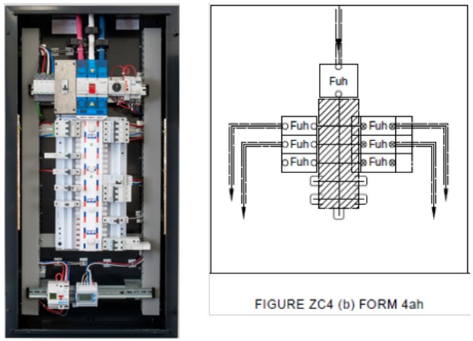
Figure 9 – ZC4 (b) Form 4ah (Ref: AS/NZS 61439.2: 2016) compared to equivalent panelboard
SECTION 4: MAIN BUSBAR TEMPERATURE RISE
In the previous AS/NZS 3439.1 standard, Table 2 specified the temperature rise limits for all components and busbar systems within the enclosure. The maximum permissible absolute temperature rating of the main busbar was limited to 105⁰C.
In comparison, the new AS/NZS 61439.1 Table 6 note (g) allows for the main busbar to operate at 105K rise above ambient.
Theoretically, this means that the main busbar can operate at a much higher temperature, allowing greater current carrying capacity. However, at higher temperatures the copper busbar will potentially anneal and reduce its mechanical strength.
Copper for Busbars Publication No.22 (page 6) states that:
- Copper bar will “soften” at temperatures above 150 ⁰C
- Copper can operate successfully at 105⁰C for periods of 25 years, and can withstand conditions as high as 250⁰C (under short circuit) for a few seconds without any adverse effects; i.e. the hardness properties are little changed from new copper
Comparative lifespan values for busbar operating at a continuous temperature of:
- 105⁰C = 20 to 25 years
- 110⁰C = 17 to 20 years
- 130⁰C = 11 to 18 years
There are additional considerations when a higher continuous current carrying capacity is designed for a section of busbar:
• Does the connected switchgear require additional derating?
• What is the insulation temperature rating of the busbar supports and other attached conductors and cables?
• What is the impact of the additional heat on other materials and adjacent equipment?
• What is the expected peak in ambient temperature and the expected lifespan of the design?
Once these considerations are taken into account, there are potential commercial savings to be enjoyed by extracting a higher continuous current carrying capacity from a section of busbar. Let’s apply the new standard to a section of 2 X 100 X 10mm busbar in the comparison of Figure 10.
Figure 10 is an extract from the Cubic Projecting manual. Based on tested results, this table specifies the temperature rise that can be expected on the main busbar for different nominated current carrying capacities. Figure 11 has been extracted from the Galaxy Free design software, which calculates the ambient temperature within an enclosure when all components and conductors are fitted and an IP rating and ventilation configuration has been specified.
In this instance, the ambient temperature within the enclosure is 74⁰C on a base ambient of 40⁰C (i.e a rise of 34K).
When we apply AS/NZS 3439.1 the absolute maximum operating temperature of the bus bar is deemed to be 105⁰C, irrespective of the external ambient temperature.
In Figure 10, we note that at 2500A current draw, the 2 x 100 x 10 bus bar will rise 30 K above the internal ambient temperature of 74⁰C, resulting in an absolute operating temperature of 104⁰C Therefore, the bus bar rating is 2500A in this instance as it does not exceed the 105⁰C limit.
When we apply AS/NZS61439.1 the absolute maximum operating temperature is 105 K rise above the nominated external ambient temperature, which is normally 35⁰C or 40⁰C. In this example, we’ve opted for 40⁰C.
In Figure 10, we note that at 3100A current draw, the 2 x 100 x 10 bus bar will rise 45 K above the internal ambient temperature of 74⁰C, resulting in an absolute operating temperature of 119⁰C.
Therefore, the bus bar rating is 3100A in this instance. However, in the absence of tested verification, Annex N from AS/NZS61439.1 can also be used to determine the current carrying capacity of a selection of copper busbar sizes. In this particular instance, the same 2 X 100 x 10mm bar is rated at 1612A.
RESULT: Three different verified ratings are possible for this example, using the same busbar in the same enclosure. The rated current carrying capacity is:
- 2500A when applying AS/NZS 3439
- 3100A when applying AS/NZS 61439
- 1612A when applying AS/NZS 61439 Annex N
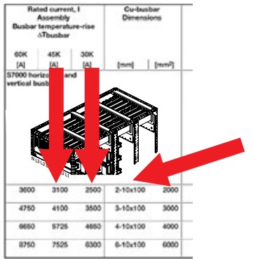
Figure 10 - CUBIC S7 000 main bus current carrying capacity
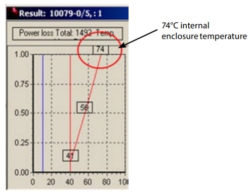
Figure 11 - Galaxy software calculated heat rise
SECTION 5: ARC FAULT MITIGATION
The new AS/NZS 61439 standard now accepts IEC/TR 61641 as an alternative to the traditional arc fault containment tests as defined in Appendix ZC and ZD. IEC/TR 61641 applies techniques commonly used for high voltage applications. In both instances, the end user and switchboard manufacturer agree to the testing criteria. Both are equally satisfactory in providing arc fault testing results in accordance with customer requirements. The arc fault protected space is represented by either a 40GSM weighted fabric curtain (AS/NZS 3439) or a 150 x 150mm square matrix curtain (TR 61641). During the arc fault test, this barrier must not ignite or be struck by any part of the tested enclosure (see images). For more detailed information on arc faults or arc fault mitigation techniques, please refer to Technical News Issue #56. The fundamental differences are noted in the table below :
IEC/TR 61641
- 150mm x 150mm squares, 150GSM
- Top, front, sides to be selected
- 300mm distance from board
- Multiple points for arc test
Appendix ZC/ZD
- One large single curtain, 40GSM
- Front only
- 250mm distance from board
- Tester decides where arc is initiated (i.e. may only be load side)
CONCLUSION
The new AS/NZS 61439 series of standards has been developed and refined for decades, and represents the best possible solution for your switchboard requirements. Remember:
Use checklists wherever possible. The most important tables are:
– Annex C User Template
– Annex D Design Verification
– Table 13 Short Circuit Verification
- PTTA and TTA definitions have been replaced with verification
- Verification – Use Annex D Checklist; verification can be completed by method of test, comparison to a tested design and/or by calculation, using AS60890 and IEC 60865-1
- Understand the implications of operating copper busbar at 105⁰C VS 105 K (new for AS/NZS)
- Forms of Separation – Choose the Form of Separation to suit the maintenance requirement of the assembly once it is in use. New images have been included to assist in selecting forms of separation when chassis systems are used, Australian version (“i” and “h”). Appendix ZB (AS/NZS 61439.2) describes forms of separation
- Arc Fault – Apply existing Australian ZC, ZD or alternatively TR61641
- Appendix ZA in AS/NZS 61439.1:2016 lists all the variations between the AS/NZS standard and the IEC equivalent or why it is based.
*Associated Technical News:
- Technical News Issue #43: Is your switchboard in good form
- Technical News Issue #56: Electrical Arcs, Beauty and the Beast
- Technical News Issue # 57: The Power of Copper
So whilst there is a 5 year sunset clause on the use of AS/NZS 3439, we recommend that you review your current specifications and seek to adopt the new standard as soon as practical to enjoy the benefits of a simpler, clearer standard.