breadcrumb
Content SDK component is missing React implementation. See the developer console for more information.
INTRODUCTION
When a circuit breaker is installed in a power distribution system, unfortunately once the switchboard is put into service, the majority of times it is then forgotten. Consideration needs to be given to the events which occur in the life of a circuit breaker. Whilst this is important in industry and process applications where there is a high investment in infrastructure or potential high losses due to lost production, the safety of personnel has to be considered in all installations.
CONCERNS OVER BREAKER HEALTH AFTER TRIP EVENTS
When a circuit breaker trips for any reason, how do we know what condition it is going to be in, to safely reset it to reconnect circuit power? The truth of the matter is, unless the cause of the trip and magnitude of the fault current are known or the circuit is thoroughly examined, on the surface we can only guess and roll the dice. Circuit breakers are devices that protect conductors from many different types of fault conditions. Earth leakage, overloads, high inrush events, low level short circuits and high level short circuits are all “faults” that can trip circuit breakers. Circuit breakers may also trip due to process control requirements for isolation and safety through activation of shunt trips or UVT coils. The major issue concerning industry is not knowing the cause of the trip, breaker condition or the service history of the breaker, especially during a critical process run. There is a risk in resetting the breaker without any idea of its service history.
INSTALLATION SERVICE CONDITIONS AND REQUIREMENTS
Each of our industry/business sectors have its own operational characteristics and priorities along with comparative service conditions. In this paper we will consider only industrial applications as the inclusion of commercial and domestic installations would over complicate an already complex subject. In the industrial sector, the most demanding applications exist in heavy manufacturing, commodity production, and mining. The priority in this area is for maximum uptime. In other words, the least disruption to production given a motor overload or circuit breaker trip. Reasons for the tripping of the protection devices are many and varied in the industrial sector, it is often not easy to identify what caused the trip:
- Earth leakage
- Overload
- Machinery jam/motor locked rotor
- Arcing fault or high level short circuit
- Protection device failure/out of specification/mal-adjustment
So under these conditions and possibilities, who determines the cause of the trip? On what basis is this determination made and what judgements are needed to justify any actions that will lead to reinstatement of the circuit to allow production to run again?
The fault type may be undetermined and not investigated due to a number of circumstances:
- The production priority is to reinstate the circuit as quickly as possible to allow the process to continue and not to stop production or impinge on quality control limitations. Therefore the breaker is reset without analysis of the cause of the trip.
- The operator may be untrained in electrical theory and reset the breaker without alerting the appropriate technical personnel. This could be due to inadequate training or contingency procedures.
- Electrical/maintenance staff inadequately trained in technical aspects of protection device operation and behaviours.
There may be many other reasons however the possible consequences of resetting a tripped device without knowledge of the cause of trip plus the failure to record the event as such, may be significant.
WHAT DO WE NEED TO KNOW?
The first thing that needs to be understood are the “knowns”. These are the limits of the circuit breaker’s endurance according to mandated tests to determine suitability and compliance to switchgear standards.
There are a number of international standards that determine a Moulded Case Circuit Breaker’s performance or rating. The standard IEC 60947-2 is the test standard for Moulded Case Circuit Breakers (MCCB) and Air Circuit Breakers (ACB). IEC 60898 for DIN Miniature Circuit Breakers (MCB), AS 3111 for NEMA ratings and AS 61009 for Residual Current Circuit Breaker (RCBO).
Moulded Case Circuit Breakers are rated for their maximum interruption capacity, or Icu (Interruption Capacity Ultimate) and Ics (Interruption Capacity Service) as part of their compliance to standards for suitability and safety.
The Icu test consists of the breaker being closed when a full bolted fault short circuit of a pre-defined value is applied.
The breaker should clear (trip) and after a 3 minute cool down period the breaker is closed back onto the existing fault. For the Ics test the breaker is allowed to cool for a further 3 minutes after the second trip event and closed back onto the fault.
If the circuit breaker is damaged, ignites or discolours a piece of test cloth placed in front of the breaker, it fails the test at that nominated fault level.
The Ics test is often done at a reduced level to the Icu test because of the additional stresses caused by the additional short circuit interruption.
Some typical values with MCCBs can be Icu = 50kA/Ics = 25kA for example. Confusion arises where the device may be rated for 50/25, the fault level at the switchboard is 35kA and a fault occurs to trip the breaker. What was the “actual” level of current that the breaker interrupted?
TEST STANDARDS VS. REALITY
The test standards only cover limited trip events at high levels. There are no tests performed for “out of spec” operations such as multiple breaker trips on instantaneous current levels above say 14 x the breaker In rating (125A breaker tripping on say >2000A low level short circuit).
The issue with the reality of, in particular, marginally rated breakers on motor start circuits (premium efficiency motors especially), is that although the breaker does not experience a true short circuit that causes a trip, it can experience contact separation on inrush. This contact separation can cause contact material erosion, arc chute carbon and conductive residue deposits and possible contact welding.
Intermittent short circuit events such as moisture tracking and rodent contact can cause similar phenomenon in the field as the low level short circuit current “clears” the root cause of the fault but has an effect on the contact system of the breaker, this sometimes includes welding of the contacts.
If the cause of the trip event is not known or the magnitude of the trip current is not evident, there are dangers if the breaker is reset without examination or some “testing” to determine the health or otherwise of the breaker.
CIRCUIT BREAKER BEHAVIOURS
There are many different types of circuit breakers used in our industrial, commercial and domestic sectors. These include:
- ACBs for heavy current (630 amp to 6000 amps) as incoming protection and large load distribution in industrial and large commercial installations
- MCCBs for incoming mains on commercial installations and large load distribution in large commercial and industrial installations
- MCBs including RCBOs for minor sub circuit supply in commercial and domestic installations
Along with the different styles of circuit breakers there are many different behaviours given a particular set of circumstances, for each of the styles.
In broad terms there are “current limiting” circuit breakers, and “non-current limiting” circuit breakers.
In the major types used for power distribution, non-current limiting types include miniature breakers manufactured complying with NEMA standard and ACBs.
Current limiting circuit breakers include the DIN MCB, RCBO, and MCCBs. MCCBs are available in Thermal Magnetic (Type A) and Electronic (Type B) styles.
IEC / AS 60947-2
On load and off load operating cycle testing is one of the durability measures quantified under the standards.
Figure 1 below shows the number of switching cycles for each current rating/frame size of MCCB, recommended both on load and off load. It also specifies the test sample maximum time delay between operations when loads are applied. This is to “normalise” contact temperatures in loaded operation situations.
The tests in no way simulate real life operating expectations but offers a yardstick to assess under conformal test criteria. The tests do however give a reasonable expectation of mechanical and light duty operations.
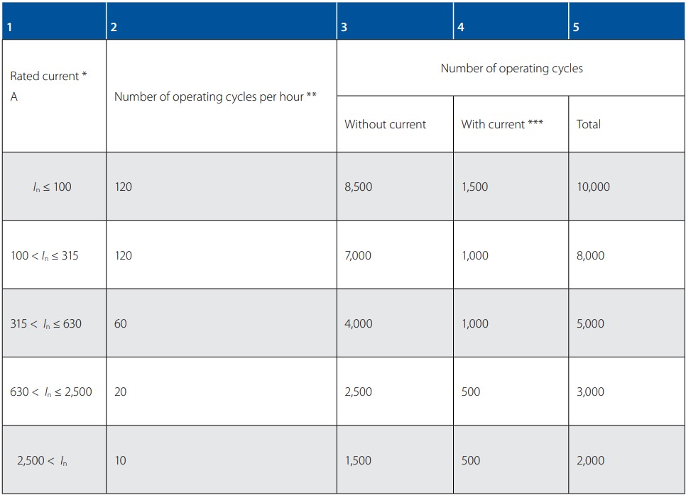
Figure 1: Number of operating cycles
* This means the maximum rated current for a given frame size.
** Column 2 gives the minimum operating rate. This rate may be increased with the consent of the manufacturer, in this case the rate used shall be stated in the test period.
*** During each operating cycle, the circuit breaker shall remain closed for a sufficient time to ensure that the full current is established, but not exceeding 2 s.
CIRCUIT BREAKER TESTING
There are a number of tests that can be performed on circuit breakers to help determine their condition against a new device. Without actually opening the breaker to do a visual inspection on the contacts and other components and mechanisms, contact resistance can be measured against the average “new” device contact resistance. Low readings can mean contacts are in good condition or they are worn but the carbonised silver oxides are conducting and surfaces have “keyed or bedded compatibility”.
The worn condition may deteriorate rapidly if so and the contact resistance test is only one indicator. Another measured indicator is resistance between poles. Carbon produced by arcing can coat the contact arc chamber and may begin to track between poles if the deposits are heavy. Tracking over time may cause phase to phase discharge and depending on the feed direction of the breaker may require the upstream protection to clear the fault.
For guidance with expected values in these tests and specific test procedures, consult with your supplier or manufacturer. Different types of breakers and different current ratings can expect different resistance results.

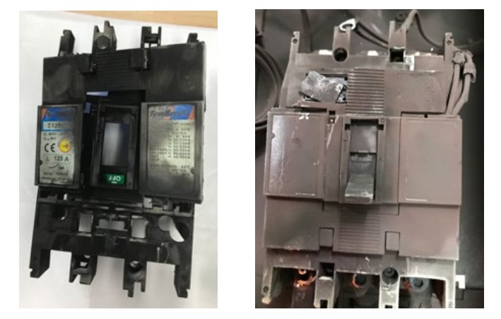
Carbon pollution caused by external arcing incident. Zero contact erosion, however breaker tracking resistance low between phases. (Notice line side terminal damage caused by external arcing).

Notice, breakers is “TRIP” position, however contact welding can cause arc fault currents to continue to flow in the circuit.
TOOLS TO ASSIST
Modern breakers can have electronic trip units, with memory retaining the cause of trip (recording the current seen on each phase at the time of the trip signal or the greatest value in the xx cycles preceding the trip). For example, the Terasaki ACB over current relay records these current values and holds them in a non-volatile memory. A similar record occurs with the Terasaki XOW series of MCCBs. The OCR stores the cause and current values of the last 10 trip events. The maintenance sub screen items for the electronic OCRs are shown below in Figure 2.
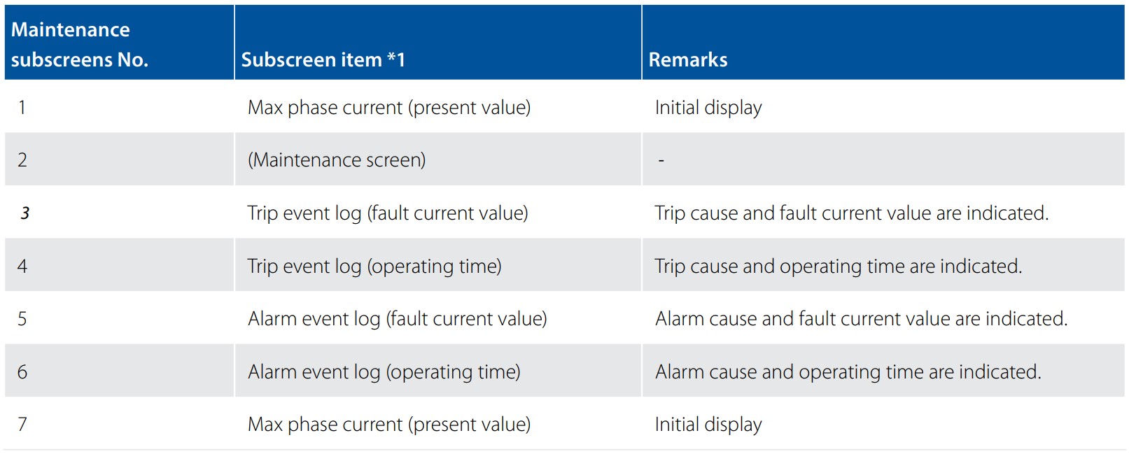
Figure 2
Another indicator of breaker/circuit health is contact temperature indication.
Some MCCBs and ACBs have this function available as an input measurement to the OCR with accumulated maximum values, time and date stamped for analysis. The register is also available as a “spot scan” to give a performance indicator in conjunction with current throughput to gauge contact condition.
An elevated contact temperature often means they have been damaged in some way and may not be fit for service.
For data acquisition, either spot viewing or via communications and SCADA, some configuration examples are shown in Figure 3. Some installations may lend themselves to centrally monitored parameters where constant information updating and decision making is performed by engineering administration.
Other decentralised applications may give more practical functionality where decisions are made on the factory floor.
Assuming proper training is given to those authorised to reset tripped breakers, the trip history can be read locally.
The OCRs may hold details of the last 5 or 10 trip events.
It is of course possible to employ both systems to improve the integrity of the decisions made and the recording of events and actions to track history and any resultant outcomes.
Armed with real information, smart decisions can be made that can reduce risk, improve safety, reduce downtime and greatly increase system reliability.
Modern technologies now make it possible to monitor, detect and evaluate via comparator, excess contact/internal phase component temperature.
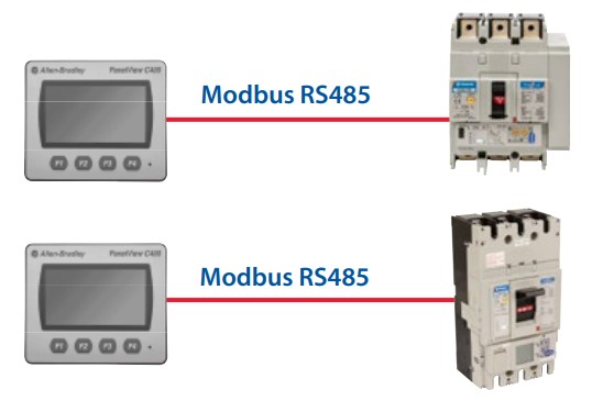
Figure 3: MCCB with Panel Mounted Screen
TRIP CAUSES AND INDICATORS
The trip causes may all be due to overload. If this is the case, as long as there are no physical signs of overheating on connections, conductors or other hardwired items, there is generally no good reason to not reset (the cause of the constant overload conditions not withstanding of course).
If the trip causes and currents show an elevated current at time of trip, (250 Amp breaker with a current at time of trip reading over the instantaneous setting of the breaker) there may be cause after say 3 trips to remove the breaker for internal examination, service and testing. This may reveal issues to do with the nature of the trip that can be helpful in determining possible mechanical problems or partial insulation breakdown/earth fault issues that could be serious if left unchecked.
If the trip current is higher than 15 x In (3500A) the breaker should be removed immediately and tested/replaced to avoid a possible arcing incident and extensive damage to the infrastructure or persons.
Without accurate information such as outlined above, we would only be guessing as to the health or otherwise of the circuit breakers.
By resetting the devices we risk severe damage occurring and the possible danger to health and safety of operators and electrical personnel.
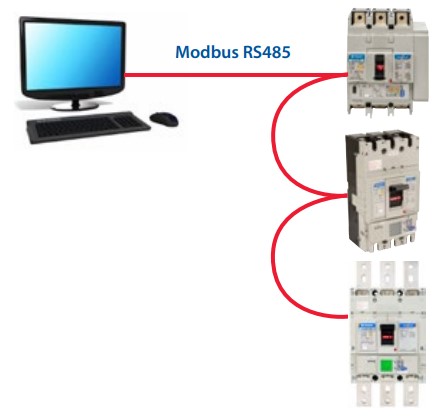
Figure 4: MCCB with centrally monitored parameters
INSTALLATION
With all protection devices, it is imperative that installation instructions are adhered to. The devices are tested with various orientations and various accessories fitted (such as phase barriers and/or terminal covers) and offer the performance stated in specifications or achieved to the required standards when installed in this way.
Installation of circuit breakers without observing proper clearances, mounting orientation, current flow (line and load) or fitting of phase barriers may cause undesired results, such as arc exhaust chamber ionised gas emission ignition.
To avoid conductors overheating, especially when mounted in tight form MCC drawers or compact enclosures, care needs to be taken to ensure adequate connected conductor size and length is connected to ensure heat can be conducted away from the breaker internals and adequate cooling of the conductor can be achieved.
SUMMARY
The performance and reliability of any electrical system relies on sound design, installation and maintenance of devices in the system. Failure to have adequate reporting procedures, operational controls and strict procedures in place can cause undesirable consequences, such as equipment under performance or failure. This can lead to serious interruption to process and production, system damage and monetary losses, and in worst cases personnel injury.
Over specifying protection devices can lead to performance issues under lesser “fault” conditions which in turn may lead to undesirable connected component damage, such as welding, contact lift and degradation and high contact impedance.
In critical and continuous production installations, devices capable of monitoring and imparting information and historical incident recordings are very useful in determining possible equipment condition and serviceability after one or more fault events, whether or not an interruption was caused. Consultation with experienced NHP Application Engineers and Technical Specialists will give the best advice on the most suitable circuit breakers to ensure reliability, safety and less incidental process downtime for the electrical system.