breadcrumb
Content SDK component is missing React implementation. See the developer console for more information.
ABSTRACT
This edition of Technical News will cover the phenomena of Arc Faults in electrical installations and the measures that can be taken to reduce the likelihood of injury from these events.
The main concepts include isolating the operator from the switchroom, operational procedures, the design of the installation and arc detection technology.
This Technical News illustrates that there are many options available to mitigate harm to operators and damage to installations. However, these measures need to be installed, commissioned and maintained correctly for effective protection.
INTRODUCTION
An arc fault is usually initiated by either a breakdown of insulation or a foreign object (such as a hand tool) causing a conduction path through an air gap in a switchboard. When this occurs, an arc is formed between phases or phase to ground.
The potential danger of arc faults in electrical installations is well documented, with a growing number of case studies and anecdotal evidence to show that precautions and design considerations with arc faults in mind must be completed for any electrical installation.
The consequences of an arc fault include significant damage to switchgear, conductors, switchboards and the installation. However, the biggest consequence is the injury or death of operators in the area.
The best form of protection for personnel working in an electrical installation is to reduce the time spent in the area of potential danger. The area of danger is not necessarily an extremely hazardous place for the operator to be but has the potential to cause harm. This is analogous to a worksite that requires hard hats to be worn by workers. The most likely time for an incident to occur in a switchroom is during electrical and mechanical operations, such as switching, isolation and racking of larger circuit breakers.
Time spent in a potentially dangerous area can be minimised by utilising common accessories for switchgear which facilitate remote operating such as motor operators and open/close coils. There are also methods available to complete the racking of circuit breakers remotely. These can be used to remove the operator from the switchroom when switching and racking operations are occurring.
Other forms of protection can also be utilised to reduce injury from such events. The use of technology to detect arc flashes and reduce let through energy are also available. These can be used to limit an arc flash within a switchboard to prevent injury to operators. The costs associated with installing this technology are insignificant compared to compensation, downtime and repairs for any installation where an arc fault event occurs.
SAFETY MEASURES – OPERATIONAL PROCEDURES
Effective procedures for operators in large electrical installations can avoid arc fault and other electrical hazards, however, these procedures need to match the site requirements and need to be implemented as prescribed. Lockout Procedures Switchgear lockout facilities, as shown in Figure 1, have been available for many years. However, these facilities are only as strong as the system put in place to manage them. Complacency in practice and misunderstanding of the exact nature of the lock out in the electrical system are the main areas for concern.
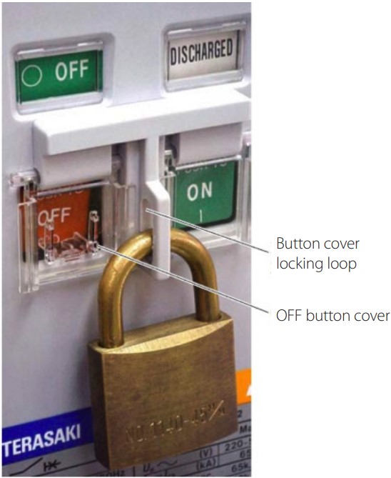
Figure 1: Using a padlock to lock off an air circuit breaker (ACB)
Correct lockout and tagging of equipment and switchgear by all personnel in the potential area of danger can ensure that power is safely returned to the area when all operations are complete. Lockout is not only restricted to isolation or control of energy; safety guards and interlocks can also be utilised in these environments. For example, many circuit breaker manufacturers offer padlock attachments for main circuit safety shutters inside carriages of withdrawable circuit breakers (see Figure 2). This facility ensures that the operator cannot accidentally access live terminals in the breaker.
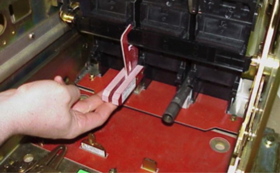
Figure 2: Carriage safety shutter padlock device being installed in an ACB.
Larger circuit breakers also have the provision for position padlocking (see Figure 3). This is also an effective locking out procedure as the main circuit is disconnected as soon as the circuit breaker is moved out of the connected position. This locking then ensures that the breaker cannot close a circuit as the main power circuit is disengaged from the breaker closing mechanism. This avoids any ‘accidental’ closing of the main circuit, via any local or remote means.
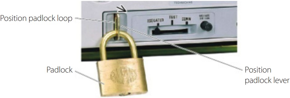
Figure 3: Using a padlock to lock an ACB in the ISOLATED position
The best method for ensuring that lockout procedures are followed as prescribed is regular training and policing by site supervisors. For larger electrical installations, formal meetings with all operators should also be carried out beforehand to address any questions or concerns over the lockout and other safety procedures.
Maintenance Mode settings
The reduction of let through energy is also an important method of reducing potential injury from arc fault incidents. With a reduction in let through energy, the size and duration of the arc will be reduced.
A simple means for the reduction of let through energy is a temporary ‘maintenance mode’ for the settings of circuit breakers upstream of the area of danger. This maintenance mode would involve changing the instantaneous (or magnetic) setting of the circuit breaker to a low level, for example, double the rated current of the circuit breaker.
This maintenance mode would have a temporary effect on the selectivity of the electrical installation, but this would only be engaged when operators are downstream of the switchgear. When effectively implemented, this is a simple way of reducing severity of any arc fault when operators are in the area.
Personnel Protection Equipment (PPE)
There are many suppliers for PPE in potential arc fault situations. These usually consist of gloves, suits, masks and other protective apparel. The ideal situation is that the operator is never in an area of potential danger.
This safety equipment can be very cumbersome, difficult to get in and out of, uncomfortable, hot, difficult to work in and usually very expensive. These difficulties lead to sites avoiding any work in areas that require this PPE as it is too difficult to organise and to carry out.
However, despite these concerns, Arc Flash PPE is still in some situations, such as HV line work. In these situations the PPE must be utilised and maintained as necessary (see Figure 4).
SAFETY MEASURES – REMOTE OPERATION
Remote operation of switchgear is also an effective safety measure against arc fault injuries. The safest place for an operator during switching or racking of circuit breakers is outside the switching room.
Remote closing, opening and monitoring
Circuit breaker manufacturers have been able to offer remote opening, closing and spring charging options for their products for many years. This can range from directly energised coils and motors, to remote control over communication protocols. This means that an operator can be in another room, or even building, to the switchgear, eliminating any risk to their safety.
The remote monitoring of circuits also provides important feedback to the operators as to where potential danger can lie. This feedback is usually in the form of electrical circuits, such as auxiliary switches, communications protocols from switchgear/ loads and metering systems. This remote monitoring of electrical installations can be used for operators to accurately identify the potential dangers at any given time and allow them to make informed decisions about entering potential areas of danger.
The use of automation equipment in opening and closing switchgear has also become popular and cost effective in recent times. An appropriate Human Machine Interface (HMI) can be used as an observation and control point for operators, allowing central control of a facility from a central control room (see Figure 5).
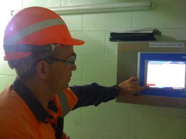
Figure 5: A site engineer uses a HMI to view the status of the ACBs in the adjoining switch room.
This type of control is well suited to any sparsely laid out installation as one operator with very basic training can control the entire installation from one location. This avoids the need for teams of operators to visit numerous switchrooms for simple switching procedures. A HMI is also well suited to include a single line diagram of the installation, so that loads on each circuit are easily seen and decisions can be easily made regarding switching of loads in the system.
This type of control is well suited to any sparsely laid out installation as one operator with very basic training can control the entire installation from one location. This avoids the need for teams of operators to visit numerous switchrooms for simple switching procedures.
A HMI is also well suited to include a single line diagram of the installation, so that loads on each circuit are easily seen and decisions can be easily made regarding switching of loads in the system.
Remote Racking
The manual in and out racking of circuit breakers also represents a point in time where there is some dynamic disturbance through a switchboard (see Figure 6). The simplest example of this danger would be a tool left inside the switchboard that drops on to conductors from this mechanical movement and causes an arc.
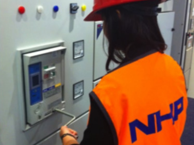
Figure 6: A maintenance worker manually racks the ACB from the connected to the isolated position.
There are now options for larger circuit breakers to be remotely racked in and out of position. Again, this allows the operator to be out of the area of danger or even in a different room.
The control of remote racking devices is usually via a pendant, but wireless control options can be used to completely isolate the operator from the area during racking. Quality remote racking devices are also battery powered, so that the device is electrically isolated from the installation, and there are no hazardous power leads passing through the switchroom.
Remote racking devices can also feature an integrated air circuit breaker (ACB) body lifting trolley. The lifting of ACB bodies can also be a difficult OH&S issue, as common sizes can weigh between 40-70 kilograms. The breaker bodies also need to be carefully moved as these are a protection device, and as such, an adjustable level platform is ideal to place an ACB body on (refer to Figure 7).
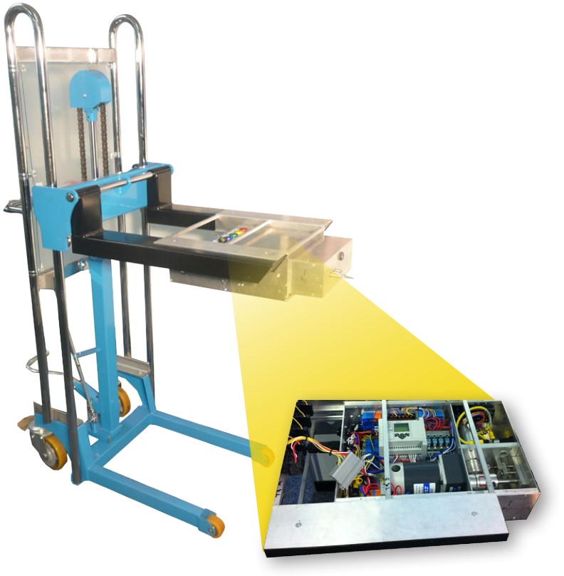
Figure 7: NHP’s remote racking device
SAFETY MEASURES – CARE OF SWITCHGEAR
The safety of an installation is directly affected by the level of maintenance that the breaker experiences over its life cycle. There are a number of different ways that the switchgear and installation can be kept in a safe and effective operating condition. The likeliness of an arc fault event is reduced with appropriately maintained protection devices.
Regular Servicing
Main incoming circuit breakers are commonly in operation for 20 to 30 years. Over this time, as with any electromechanical device, lubrication will dry out, accessories will begin to fail, corrosion of some parts may occur and internal contact resistance will increase.
Most manufacturers suggest at the very least to open and close a large breaker a few times at six month intervals. This will keep the lubrication moving and work the mechanical parts such as springs. This will also be an opportunity to see if anything has changed in the operation of the breaker, such as noises or visual indications of damage.
An accredited service technician can thoroughly check the breaker for any potential problems, inspect and clean contacts, and test the switchgear before an event occurs. Regular inspection of electrical installations is also essential to the maintenance of a switchroom. Inspection for large dust deposits, corrosion, signs of wear and tear, condensation and heat damage should also be carried out as these can affect the performance and operation of the switchgear.
Spare Circuit Breaker Bodies
Larger circuit breakers with a withdrawable assembly are well suited for regular servicing. The breaker body or withdrawable component in quality air circuit breakers contains the critical components of the circuit breaker:
- Spring loaded clusters for main circuit connection
- Fixed and moving contact assembly
- Accessories such as charging motors, over current protection and open/close coils
When a spare body is kept on-site, this can be cycled with circuit breakers in service, so that these critical breaker components can be fully serviced away from the switch room.
With this system in place, circuit breakers can be kept in serviced condition with minimal shut down and disturbance to installation. This system also covers the situation where a breaker may have cleared a large fault and needs to be inspected. The body can easily be swapped for the spare within minutes.
SAFETY MEASURES – DESIGN CONSIDERATIONS
The design of a switchroom and switchboard also has a large impact on the potential harm being caused to personnel in close proximity due to the initiation of an Arc Fault.
Forms of separation as defined in AS/NZS3439.1:2002 allow for switchboards to be built which provides varying levels of safety and protection against an internal arcing fault. This built-in separation of components and live terminals means that the likelihood of propagation of an arc fault is significantly reduced as access to exposed busbar is significantly reduced. The Australian & New Zealand wiring rules, AS/NZS3000:2007 further defines that switchboards >800A are required to have a form of separation of at least Form 3b or higher.
AS/NZS3439.1:2002 also defines test procedures (Annex ZD), which allows for complete switchboard systems to be built to withstand arc fault within the enclosure itself (see Figure 8). The benefit of a type tested switchboard which contains certification to Annex ZD, stipulates that personnel are guaranteed that under an arc fault condition within the switchboard, a propagating arc fault cannot escape from the switchboard enclosure which may cause injury or even death.
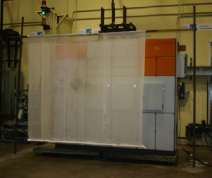
Figure 8: A CUBIC switchboard undergoing arc fault containment testing.
The switchboard segregation is only effective if maintained and regularly inspected, ensuring that no breakdown of the insulation and segregation barriers are still effective. Switchboards can also be compromised by unexpected influences which could occur in a plant such as chemical fumes or water ingress.
ARC FLASH CALCULATION AND PPE RECOMMENDATIONS
The detection of arc faults via current sensing is a complex issue. Arc faults by their nature are unpredictable and erratic. The current observed during an arc fault is not comparable to a phase to phase or phase to ground fault.
Phase to phase and phase to ground faults are relatively straightforward: a foreign conductor completes the circuit, bypassing the load and the resulting resistance of the circuit immediately drops to a low value. This low resistance causes a large increase in current. This large jump in current is the basis for regular overcurrent tripping by circuit breakers.
Arc faults, on the other hand, can go through a number of different stages. An example that demonstrates this would be the dropping of a tool across two poles of the load side connection of a circuit breaker.
Phase 1 – The tool lands on the conductors, the new path for the electricity has low resistance and a current spike begins.
Phase 2 – The current spike causes magnetic repulsion of the tool, this causes the tool to be thrown from the poles of the circuit breaker. An air gap opens between the tool and the conductors, forming an arc. The air gap introduces a resistance in the fault, which causes current flow to drop.
Phase 3 – The tool is thrown from the fault and the arc continues between conductors. The conductors begin to melt and become gaseous, the air also becomes ionized.
These effects cause the resistance to drop once again, increasing the current observed. These three steps in an arc flash directly contradict the traditional overcurrent protection featured in circuit breakers. The current observed by the circuit breaker may not cross the trip curve until the third phase of the fault, by which time much damage may have already be done (see Figure 9).
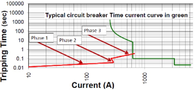
Figure 9: A typical circuit breaker protection curve in green and the approximate behaviour of an arcing fault in red.
AS/NZS 3000 FORMULA
AS/NZS3000:2007 clause 2.5.5.3 defines the formula for calculating the trip curve settings for breakers to clear an arc fault when it occurs.
This formula is based on the premise that an arc fault is approximately a third of the value of the prospective fault level at the point of initiation.
The formula itself has its origins from one of the supply authorities, and has been used for this purpose for a number of years. To minimise the damage that an arc can cause to a switchboard, the main circuit breaker trip curve must be set to clear a calculated arc fault within a specific time frame.
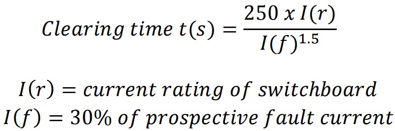
Assuming 20kA for a 1250A switchboard

This result means that a 6kA arc fault needs to be cleared in 672 milliseconds.
Although this does give some guidance to switchboard designers, it must be noted that an arc fault for this length of time would still cause significant damage.
UTILISATION OF LIGHT SENSORS
An effective means for detecting arc faults is to step away from current waveforms. An arc flash releases a large amount of energy in the form of heat, pressure and brilliant, blinding light. This light is produced as the arc forms and becomes increasingly brighter as the fault continues.
Light sensors can be utilised with dedicated trip units to sense light from an arc flash and trip upstream breakers. These dedicated trip units react very quickly to the flash of light, as quick as 1mS.
The time taken for the circuit breaker to open the circuit then becomes important. Some circuit breaker manufacturers can achieve clearance in as little as 40mS via a shunt trip coil. A maximum total arc fault time of 41mS is a very good result and reduces the let through energy to a minimum. A 41mS is comparable to the instantaneous tripping time for a quality air circuit breaker.
A sample calculation is as follows:

Without Arc Detection relay:
V=440VAC, I=6kA, Time = 0.672 S
30cm: 37.5 cal/cm2
50cm: 13.5 cal/cm2
With Arc Detection relay:
V=440VAC, I=6kA, Time = 0.041 S
30cm: 2.3 cal/cm2
50cm: 0.8 cal/cm2
The calculation results in Figure 10 show that a significant reduction in PPE requirement can be achieved with the addition of an arc detection relay.
Note that “Arc Rated” means clothing designed and tested to the energy level calculated for that particular installation – a 10 cal/ cm2 rated installation requires a 10 cal/cm2 coverall, where a 2 rated installation only requires a 2 cal/cm2 coverall.
These light sensor based relays can also be retrofitted to existing installations to add extra protection to the system. The installation is relatively easy and can be carried out during a scheduled shutdown. The only requirements for a retrofit are control power and that the circuit breaker/s that need to be tripped have a method of electrically tripping, such as a shunt trip coil.
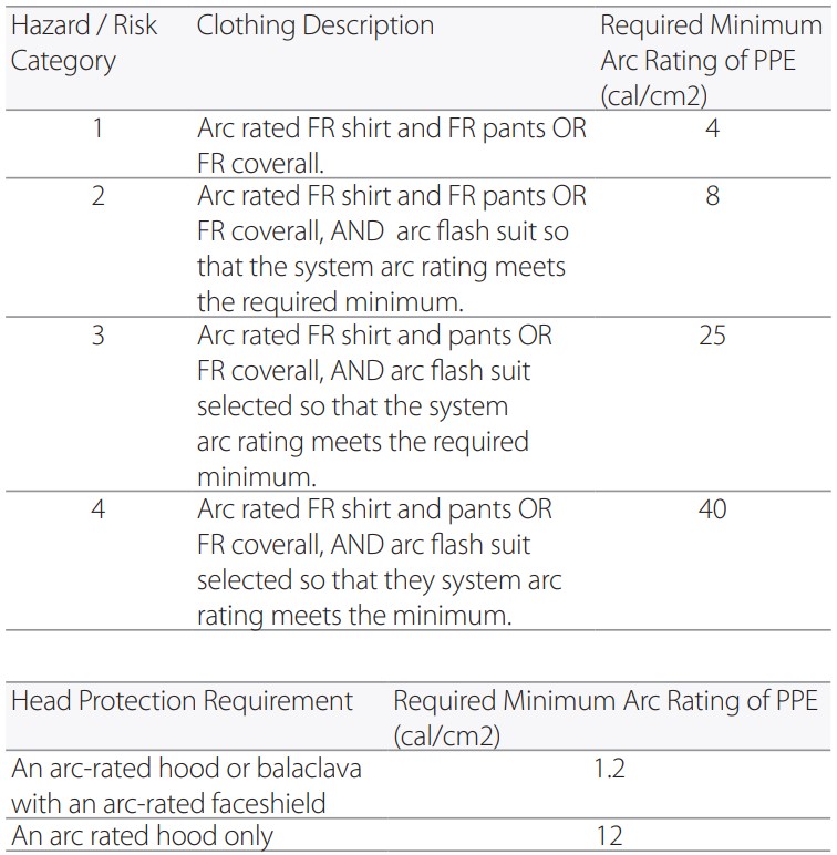
Figure 10: NFPA 70E PPE recommendations for Arc Flash
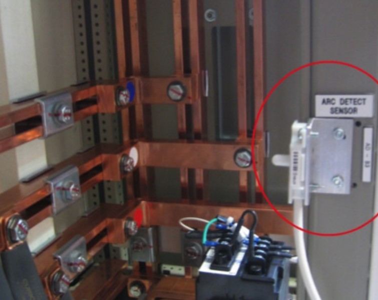
Figure 11: An arc detection relay and sensor.
SUMMARY
The incidence of arc faults can cause significant damage to installations, but more importantly, can cause significant injury or death to operators in the area.
This edition of Technical News has described some of the techniques that can be used to reduce the risk to personnel working in the area. From simple lockout procedures to arc detection relays, there are numerous ways that electrical installations can be equipped to deal with arc faults.
Implementation of these concepts can reduce damage to installations, injury to operators and costly downtime.
REFERENCES
http://literature.rockwellautomation.com/idc/groups/literature/documents/ ar/journj-ar011_-en-p.pdf
NFPA 70E - Standard for Electrical Safety in the Workplace
AS/NZS 3000:2007 – Wiring Rules