breadcrumb
Content SDK component is missing React implementation. See the developer console for more information.
The electrical industry and other industry sectors, as well as society in general, are increasingly involved in the means to improve the efficient use and monitoring of energy. The objectives of this are to reduce energy cost and usage, as well as moving towards a more carbon neutral society, with the overall aim of decreasing greenhouse gases and their harmful environmental effects.
For the electrical industry, one part of making this happen is through the use of high efficiency induction motors, which power production lines, conveyors, pumps, and air-conditioning, as well as numerous other uses. However, the speed at which well intended change has come to one sector of the industry has caused some challenging problems in other areas. For example, the development of high efficiency motors and their mandatory use in this country and other parts of the world, have impacted the reliable operation of motor control and circuit protection devices as a result of the much higher inrush currents produced by high efficiency motors.
For all suppliers of motor control and power distribution and other equipment being used in motor start applications, this represents nothing short of a dilemma which must be overcome. This Technical News discusses some of the issues which are still not well understood by many in the industry, as well as some NHP solutions.
HISTORY OF MEPS PROGRAM
The introduction of the Minimum Energy Performance Standards (MEPS) range of high efficiency motors worldwide has been an active program since 1998 in the EC, with new motors to be a minimum safety Standard Efficiency of IE1 IEC standard, and regulations for Australia introduced in October 2001 for implementation under MEPS1.
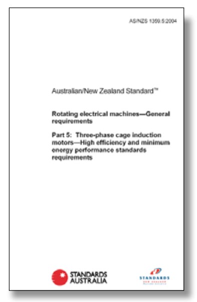
The introduction of MEPS2 started around December 2003 and regulations AS/NZS1359.5-2004 came into force around April 2006. The requirements for higher efficiency from new motors, saw MEPS2 motors designated generically as “High Efficiency” and are similar to IE2 IEC standard motors.
With Australia utilising motors from the Global Market, the implication of motors built to meet the IEC Efficiency Classes – IEC 60034-30-1, came as IE3 Premium efficiency motors began their introduction into Europe from 2009, which then began to filter into the Australian market from 2010.
The designs of each subsequent level of efficiency for these motors is based upon the “BAT” (Best Available Technologies) for manufacture of the components and design to increase the operational efficiency characteristics.
With the introduction of IE4 Super Premium efficiency design motors, as per IEC 60034-30-1:2014, it is not certain what ultimately the attributes these motors will have and what effect they will have on the electrical system.
This may pose more challenges to our industry in the future.
TYPE 2 COORDINATION
Type 2 Coordination has been extensively specified in Australia and New Zealand for many years, and is widely used in other parts of the world.
As described in AS/NZS60947.4.1 Type 2 Coordination is the coordination of motor starter components – Contactor and Overload, and Short Circuit Protection Device (SCPD) during a short circuit fault condition. The SCPD predominantly used is a circuit breaker, however, fused switches are still utilised in some applications. The devices must conform to AS/NZS60947.4.1 referring to the operational kW rating of the load, and testing on short circuit for a particular kA level (say 50kA).
When a downstream fault occurs downstream of the starter, under a short circuit condition, the SCPD limits the let through energy of the fault to a level that allows protection which ensures;
- No danger to persons or installation
- The SCPD is still operable and undamaged
- The motor contactor to be undamaged, if light welding did occur this is accepted, provided it may be separated by a simple tool, and the contacts are not deformed
- The overload shall be in operational condition, and still within calibration limits
This allows for a starter to return to service for further use, without replacement of any components that may be required under Type 1 Coordination.
Manufacturers recommend regular scheduled maintenance, for a detailed inspection to ensure the starter components will be able to function correctly in the event of a future short circuit fault.
Typical Type 2 Coordination tables list recommended tested combinations of devices used in motor starter cells or assemblies for standard motor AC3 kW ratings, covering installations at nominated kA fault levels, and supply voltages.
CIRCUIT BREAKER OPERATION
Circuit breakers utilise a number of separate mechanisms which make up their protection characteristics or trip curve.
Thermal Magnetic Circuit Breakers
When using thermal magnetic circuit breakers, the thermal trip function for low level overloads is provided by passing current through and heating bi-metal strips which consist of 2 dissimilar metal strips attached to one another. The bi-metal strips will bend proportionally if heated enough, and will push the trip bar latch, which in turn causes the breaker to “trip” which open circuits the circuit breaker main contacts.
The short circuit instantaneous trip function is achieved by a wire wound solenoid device. As the current increases in the coil winding, the magnetic flux increases in proportion to the current rise. This forces a pin to push out and unlatch the trip lever of the breaker and open the contacts.
Another effect of high fault currents on circuit breakers is that of magnetic repulsion and contact separation. Most brands of breakers are designed with a “U” shaped current path bringing opposite direction currents into close proximity with each other.
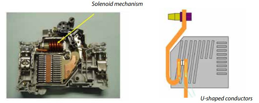
This event is crucial to a circuit breaker’s ability to reduce peak let through current by introducing impedance from the contact separation and subsequent arc. The age old “right hand grip rule”, where the direction of the thumb depicts current direction and the curl of the fingers depicts the direction of magnetic flux in a conductor, is used in circuit breaker technology to force contact separation under high short circuits, which introduces an arc between the contacts and adds impedance into the current path.
This slows the rate of rise of the short circuit current giving time for downstream breakers to clear before the upstream opens when the solenoid pin unlatches the contacts. This is a function that assists “enhanced selectivity” in circuit breakers. It is important to understand this function and the relationship between all 3 actions to fully understand the physical effects of the IE3 motor characteristics.
The speed of operation, along with the peak current limitation and reduction of I2t let through to a downstream contactor and overload during a short circuit, determines the appropriate contactor and overload combination that can be used to achieve Type 2 Coordination. If we increase the size of the circuit breaker, there will be a subsequent increase in the amount of peak current and I2t energy let through to the downstream short circuit and devices. To ensure the contactor is able to withstand this increase, we need to increase the size of the contactor to match the circuit breaker characteristic let through levels. Failure to do this would mean possible contactor contact welding to be severe and not meet the requirements of “Type 2”.
Electronic Circuit Breaker Operation
Electronic circuit breakers have no thermal element to sense temperature, so they rely on an electronic Over Current Relay (OCR) to sense current and calculate the temperature rise in connected conductors by comparing that to a pre-determined model and numerical calculation. When the desired figure is exceeded, the OCR fires an output signal that activates a miniature solenoid to trip the breaker trip mechanism.
In the case of short circuit currents, this trip function needs to be extremely fast. The OCR “samples and integrates” the values based on the “clock speed” or scan rate.
The Terasaki OCR scans at 2kHz or 2000 measurements per second. If we further break this figure down to reflect the number of scans per 50Hz cycle, we get 40 per 20 milli-seconds or 2 per milli-second. If the arithmetic “number” seen for the current reading exceeds the set figure, the breaker fires the trip pin (mechanism). This figure is based upon a much smaller value than the damage curve of any given conductor.
IE3 MOTOR CHARACTERISTICS
Premium Efficiency IE3 Motors have a 1-2% better efficiency than the IE2 motors with up to a 25% reduction in motor losses, and have a resultant higher power factor.
Improved efficiencies are realised in the IE3 motor design resulting from a combination of:
- Reducing electrical loss properties, with increased stator copper and higher conductivity rotor bars, providing reduction in I2R losses.
- Reducing iron losses, with thinner laminations of higher grade steel, providing a reduction in eddy current and hysteresis loss.
- Efficiencies in magnetic flux densities within the air gap between the rotor and stator, and other mechanical areas, resulting in a reduction in bearing and winding losses.
Different manufacturers utilise different combinations of methods to achieve increased efficiency levels required by the relevant standards.
When a motor is switched onto a source voltage, current will flow in the stator which energises the copper windings and as a result, a rotating magnetic field will be produced in the stator. This will be induced into the rotor and current will then flow through the rotor bars.
Prior to this point in time, the supply is trying to produce current in line with Ohm’s Law, with the current flow dependent on the supply impedance and motor resistance. The lower the impedance level, the higher the current flow in relation to the voltage.
The IE3 motor rotor is designed with more copper mass, hence the electrical model of a high efficiency motor has the Impedance / Resistance ratio increasing, which results in the following conditions below.
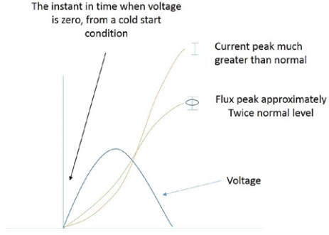
The instantaneous peak inrush, which is a momentary current transient that occurs immediately for the first half cycle, and is a multiple of the Locked Rotor Current. This is similar to the excitation of a transformer, and the highest inrush occurs when the voltage waveform is at zero.
This condition remains until a magnetic flux is established and stabilises the current inrush to the stator.
Assuming magnetic saturation does not occur, the “theoretical peak current” calculated by manufacturers is 2 x LRC x 1.414 (root √ 2).
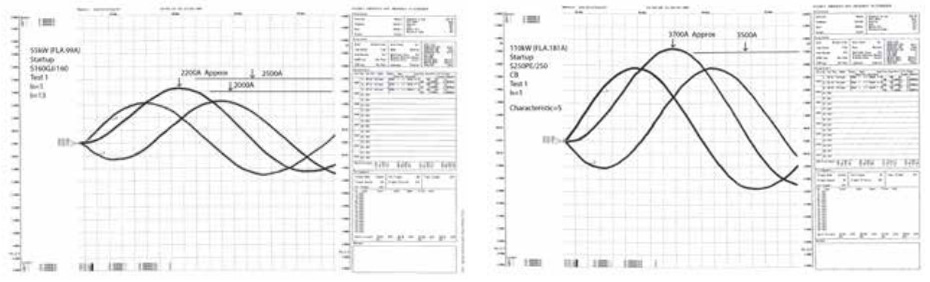
For a motor of 110kW with 180A FLC - LRC x 8, x 1.414 = 4,072 Amps.
As current is the same in all parts of the series circuit, this same high current transient is also flowing through the upstream circuit breaker and contactor / overload set. This of course effects these components as if a high fault current has occurred. The effects of this inrush on switchgear can vary from being annoying to being destructive and if it is dismissed or ignored, can be dangerous.
THE PERFECT STORM
Motor manufacturers are not obligated by the standards to publish the figures obtained relative to the Inrush Current peak (transient inrush). The spurious inrush current associated with high efficiency motor design has been the cause of circuit breaker nuisance tripping, and is an issue wherever high efficiency motors are used with DOL starting. Although high efficiency motors have been in use for many years, it is taking a long time for the industry and customers to become educated about this issue. There are numerous industry white papers and publications on the subject.
A case study:
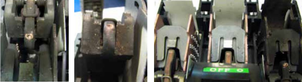
A typical example of an issue was when NHP was involved in investigating the spurious tripping of circuit breakers used in a local mining project south of Perth. After many problems during commissioning, contractors, consulting engineers, and switchboard builders, NHP were called to solve the problem of the tripping breakers. At this stage, recordings were taken with high speed low CT saturation equipment to capture the start. These recordings exposed the magnitude of the problem. We found that in some critical circuit breaker “frame” sizes there was the need to increase to the next physical frame size up. The magnitude of this current can cause subsequent release of the instantaneous trip mechanism and can cause contact separation. This occurs in more than 30% of start attempts. The contact repulsion effectively “erodes” the contact material and degrades the effective operation of the breaker due to increased contact resistance and eventual complete material loss.
The need to increase the physical size of the breaker to the next frame size also causes problems with Type 2 Coordination in motor control centres manufactured to form 3B or better.
All subsequent items need to be increased to conform to the test standards. This will in turn increase the size of the switchboard module required to house the equipment.
Now let us look at the effect this has on electronic breakers.
The problem with this event is; being so brief and low in actual “heat causing energy” and high in “magnetic flux causing energy”, the OCR sees an almost immediate drop in the level due to a number of physical causes.
- The stator has established its magnetic field prior to any critical damage causing I2t or high energy damage to conductors.
- The contact set of the circuit breaker has been subjected to this flux also and has separated a little causing impedance to lower the level of current rise for a brief moment.
Within a thermal magnetic breaker, this same level of reactive current has caused the breaker to trip. However, within an electronic breaker, the contact separation is the only magnetic influence within the breaker. The contacts separate and arc occurs, however there is no trip signal produced by the OCR and the breaker will remain closed. Is an electronic MCCB a long term solution?
This gives us the impression that the electronic breaker solves the problem of the trip during the start. On the surface this may be true, however the underlying problem is with the number The following examples are actual recordings taken from on-site tests; of events endured by the breaker which will determine the rate of long term degradation of its contacts and carbonisation of its arcing chamber and arc chutes. After numerous starts, the electronic breaker will eventually fail. The timing for this event is entirely unpredictable and could be dangerous depending on many issues.
The following examples are actual recordings taken from on-site tests;
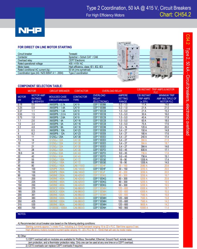
See the following example of a standard 50kA Type 2 Coordination table using Terasaki Breakers with Sprecher + Schuh contactors and Electronic overloads, configured for high efficiency motor starting.
THE REMEDY
There is no real remedy to this problem except to make changes to the connected equipment as per the recommended manufacturer’s tables.
These figures are representative of the “critical” sizes and combinations of motors and devices that need to be given special attention.
Motor Current Test Examples:
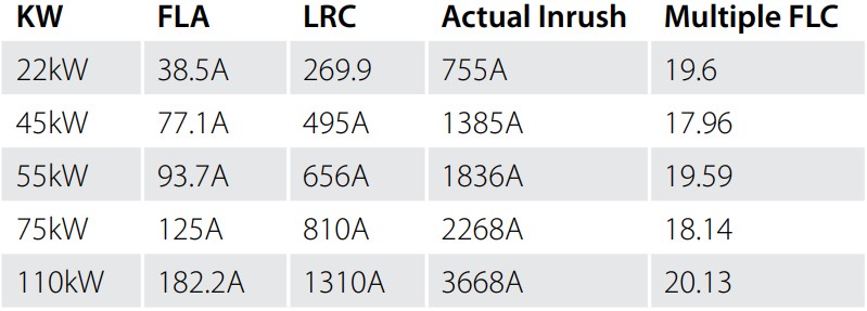
In addition, it was found that motor sizes of 185 to 220kW and 280 to 300kW also deserved reconsideration of their conforming and workable starter sets.
The component combinations for Type 2 Coordination charts were revised by NHP for certain kW ratings, where the revised MCCB selection allowed for the increase in inrush current to ensure the industry was provided with certified viable coordination combinations for all types of equipment.
This includes combinations for all voltages, fault currents, overload types, circuit breaker types and contactor models. NHP have produced tables of components especially to cover these combinations when used with high efficiency motors.
When considering future designs or replacement motors, consideration needs to be given to;
- The type of motor being replaced / or upgraded to a high efficiency design
- The compatibility of the existing connected equipment to do the job
- Available space should there need to be an “up-sizing” of switchgear due to the motor type
- Requirement for Type 2 Coordination
These conditions apply ONLY when the motor is started using Direct On Line methods. Reduced voltage starting dramatically reduces the effects of the fluxing current peak inrush. It is however, in debate presently what effects these motors have on devices, such as Soft Starters and VSDs, depending on their control methodology.
If in doubt, NHP’s Applications Engineering / Technical Services department can assist.